
Modular

sold out at the moment
ADDAC710 is a dual channel Isolated DI box and is all about keeping the sound coming from your Modular free from any undesired noisy interferences, making sure that what you’re getting from your outputs is what your Modular is actually producing. It provides galvanic electrical isolation between the Modular system and external sources preventing impedance mismatch and ground loop induced hum.ADDAC’s 710 circuit is designed around a unity 1:1 type Audio Transformer operating in the 20 Hz to 20 KHz range, this impedance matching transformer provides two fully balanced outputs (via XLR connectors).ADDAC710 is an alternative to our ADDAC800X High-End Outputs module, we redesigned the original circuit using a smaller transformer that also reduced it’s depth allowing it to fit shallow Eurorack cases.The LIFT/FLOAT/GND 3-way switch lets you choose between lift, ground or floating ground.In the LIFT position (left) the module circuit will be “lifted” to ground through a 100R resistor and a 10nF capacitor.In the FLOAT position (middle) Ground will not be shared leaving ins and outs grounds completely apart from each other fully isolating both signals.in the GND position (right) Ground will be shared between inputs and outputs, here no isolation is used.Any of these three positions may be the best form of avoiding ground loops or any other undesired interference occurring between your modular and the sound system you’re plugging it into.Try out which one of these options will work best in any given situation.DIY-Kit-Type:SMD-Kit-2. This is a Do-It-Yourself kit, not an assembled module. The kit includes all parts to build the module. It includes SMD and through-hole parts! For build guide, more info, videos etc. please check the buttons below.

only 2 left
ADDAC711 is a dual channel Isolated DI box and is all about keeping the sound coming into your Modular free from any undesired noisy interferences, making sure that what you’re getting from your inputs is what your external hardware is actually producing. It provides galvanic electrical isolation between the Modular system and external sources preventing impedance mismatch and ground loop induced hum.ADDAC’s 711 circuit is designed around a unity 1:1 type Audio Transformer operating in the 20 Hz to 20 kHz range, this impedance matching transformer provides two fully balanced outputs (via XLR connectors).The LIFT/FLOAT/GND 3-way switch lets you choose between lift, ground or floating ground.In the LIFT position (left) the module circuit will be “lifted” to ground through a 100R resistor and a 10nF capacitor.In the FLOAT position (middle) Ground will not be shared leaving ins and outs grounds completely apart from each other fully isolating both signals.in the GND position (right) Ground will be shared between inputs and outputs, here no isolation is used.Any of these three positions may be the best form of avoiding ground loops or any other undesired interference occurring between your modular and the external hard- ware. Try out which one of these options will work best in any given situation.DIY-Kit-Type:SMD-Kit-1. This is a Do-It-Yourself kit, not an assembled module. The kit includes all parts to build the module. All SMD parts are pre-soldered, only trough-hole parts to solder. For build guide, more info, videos etc. please check the buttons below.

available
ADDAC712 is a dual channel discrete gain staging amplifier, based on a famous discrete preamp board from the 70’s used in some legendary equipment. What caught our attention was the character of it’s clipping and resulting saturation/distortion.The module can be used with modular signals to add a distortion/fuzz character or as a preamp for an external source such as a line source, keyboard, guitar... It’s also a great side companion for our ADDAC711 Balanced Inputs.At the top an On/Off [BYPASS] switch routes the signal into the Effect (Up: Active) or to the bottom output gain stage (Down: Bypassed).The amount of amplification is set by the [GAIN] control, the maximum amount of amplification can be set by the user using the [MAX GAIN] trimmer.Up to ±5,5v the incoming signal will keep it’s integrity, beyond this point saturation will start to increase. At approx. ±6v a hard clipping will start to occur, this clipping also has a particular quality that at extreme levels it drifts the audio 0v bias reference, moving it upwards which results are similar to a Gate effect.In the middle, an x2 op-amp based output gain stage with a clipping LED, which monitors the clipping at the output, and an [OUTPUT] control to set the output volume.Having the top and middle gain stages provides flexibility allowing the user to completely distort the signal on the top stage and tame it’s output level with the second stage.At the bottom, input and output for both channels (left input is normalled into right input).DIY-Kit-Type:SMD-Kit-1. This is a Do-It-Yourself kit, not an assembled module. The kit includes all parts to build the module. All SMD parts are pre-soldered, only trough-hole parts to solder. For build guide, more info, videos etc. please check the buttons below.

sold out at the moment
ADDAC713 is the stereo version of our 703 Discrete Mixer. Inspired by Moog’s CP3 mixer, this is a fully discrete analog mixer and it's not, by any means, your standard breakfast mixer, although it can behave like one.This is a wolf in sheep's clothing. Despite its harmless looks there's a dark snarly soul behind that panel that wants to take your sounds into a realm of gritty gnarly growls.This new version was initially thought of as a percussion mixer, with mono inputs and panning, to allow placing percussive voices in the stereo field, while keeping channel 4 in mono for low end sources like a kick drum or Bass. In the development process we slightly changed this initial idea, adding stereo inputs for the first 3 channels, but still kept the 4th channel in mono.All four [GAIN] controls go to extreme levels, the first 3 channels also feature [PAN] controls.Feedback is used to overdrive the whole mix. As the control is turned clockwise the sound will be clipped harder until it goes completely off, this happens as feedback is increased the audio bias reference also moves up, at extreme levels it offsets the whole signal upwards until it completely goes above the top rail clipping the whole signal hence the resulting gate effect.The [MASTER OUTPUT] sets the overall output gain of the mixer, the two LEDs monitor the audio output signal.The soft clipping switch engages an anti-click circuit which adds a low pass before the output, the switch allows 3 states: Soft low pass / Off / Hard low passFeatures:• Three channels with stereo inputs, gain and pan knob• One channel with mono input and gain knob• Feedback/gate knob• Master output volume knob• Soft clipping switchDIY-Kit-Type:SMD-Kit-1. This is a Do-It-Yourself kit, not an assembled module. The kit includes all parts to build the module. All SMD parts are pre-soldered, only trough-hole parts to solder. For build guide, more info, videos etc. please check the buttons below.

sold out at the moment
ADDAC714 is a dual channel soft clipping module.Diode based passive clipping acts as a “brick wall” limiter with a fixed knee given by the inherent diode physics. A passive RC low pass circuit adds a 3,3KHz -3db low pass filter which sculpts the overall tone while also adding further character to the effect.At the top an On/Off [BYPASS] switch routes the signal into the Effect (Up: Active) or to the bottom output gain stage (Down: Bypassed).The amount of clipping is set by the [GAIN] control, it mostly works as a threshold control for how much clipping will be applied. As more clipping is applied the signal’s amplitude will also decrease, to compensate for this we set up a gain compensation stage to keep the output amplitude balanced across the Gain range.Symmetry chooses between bipolar clipping or positive clipping, this relates to the harmonics generated, bipolar for odd and even harmonics (up position) and unipolar for odd harmonics only (down position).At the second stage, an op-amp based x2 output gain with a clipping led, which monitors the clipping at the output, and an [Output] control to set the output volume.Having the top and middle gain stages provides flexibility allowing the user to completely distort the signal on the top stage and tame it’s output level with the second stage.At the bottom, Input jacks for both channels (Left input is normalled into Right input) and output jacksDIY-Kit-Type:SMD-Kit-1. This is a Do-It-Yourself kit, not an assembled module. The kit includes all parts to build the module. All SMD parts are pre-soldered, only trough-hole parts to solder. For build guide, more info, videos etc. please check the buttons below.

available
Inspired by our ADDAC701 VCO waveform mixing section, our new VC Signal Router also updates our legacy X-Fade/Panner to a stereo configuration that also allows 4 quadrant mixing.Featuring two dedicated X-faders and a stereo VCA that can also be used as a third X-Fader. All controls have their own CV inputs and dedicated Attenuverters for precision control.4 quadrant mixing is achieved by using the stereo Master as a X-fader between left and right channels, this way you can plug 4 audio sources and sweep/crossfade between each and any of them using the 3 x-faders. Plug any 4 sources (4 waveforms of a VCO, 4 LFOs, 4 envelopes...) and sweep through morph through or have them all mixed together.For other configuration types Left and Right X-fader channels can be routed through the Master stereo VCA or sent directly to the outputs. A stereo Direct input can also be routed through the Master VCA or sent straight to the outputs.The Mono Sum output always mix Left and Right outputs together allowing the possibility to use the module as a peculiar 6 channel mono mixer.It can be used for both Audio or CV Signals.Features:• 6 mono inputs• 2 dedicated X-faders with Control knob + CV Input and Attenuverter Each X-fader can be routed through the Master mix or straight into the outputs.• Master channel can be used as a stereo VCA or an X-fader• Stereo direct inputs can be routed through the Master mix or straight into the outputs.• Fully analog audio path with high quality/low noise VCAs.DIY-Kit-Type:SMD-Kit-2. This is a Do-It-Yourself kit, not an assembled module. The kit includes all parts to build the module. It includes SMD and through-hole parts! For build guide, more info, videos etc. please check the buttons below.

sold out at the moment
Here's our Phono Pre Amplifier module, connect your turntable to it and bring its sound straight into any of your patches.DIY-Kit-Type:SMD-Kit-2. This is a Do-It-Yourself kit, not an assembled module. The kit includes all parts to build the module. It includes SMD and through-hole parts! For build guide, more info, videos etc. please check the buttons below.

only 1 left
ADDAC813 is a straight forward stereo mixer. Featuring 5 stereo channels, 4 of them with attenuators, a mono send/return path for parallel processing plus stereo and mono outputs.Four channels with stereo input and gain knob. Fifth channel with stereo input without gain knob, which are the prefered inputs to cascade several ADDAC813s when more channels are needed. Master Output controls the level of the Inputs mix. Two leds monitor the inputs mix.Mono Send / Return return path allows for easy integration of mono effects in a stereo chain. Plug your favorite module through it (filter, bbd delay, spring reverb...) or any mono pedal.The Return Gain works in parallel with the Master Output, just like regular wet / dry controls.The send output can be configured to be line or synth level via a jumper in the back.Stereo output sums the Inputs Mix with the Return signal.The Mono output is the sum of Left and Right outputsEffect PedalsUsing the send output at Line level, the user can connect the send output directly into mono effect pedals and have the pedals output connected directly into the return input without the need of an attenuator/amplifier module.DIY-Kit-Type:SMD-Kit-1. This is a Do-It-Yourself kit, not an assembled module. The kit includes all parts to build the module. All SMD parts are pre-soldered, only trough-hole parts to solder. For build guide, more info, videos etc. please check the buttons below.

sold out at the moment
This small board was designed to bring some extra flexibility and customization regarding powering up a modular system.Whenever a modular system is turned on there's a current spike upon startup that will momentarily influence the PSU output and can take up to a couple seconds for the PSU to stabilize to it's stated specifications. PSUs can also have some delay between their power lines where one polarity is provided prior to the second one. They also commonly have a ramp like startup. All this is common and normally not a problem. While most modules are fine with this situation, there are others that can suffer from this and in a worst case scenario won't startup correctly. Some modules can also be sensitive to the timing of the ±12v, some may require both to arrive at the same time others won't start if -12v arrives prior to the +12v, etc.This small board allows to time the deployment of power to a specific module, it can delay each power line independently by 3 seconds, meaning that after powering up your modular it will wait for 3 seconds until it will provide power to the specific module connected to it. This delay time can also be customized by the user replacing a couple capacitors.Using this small board with more sensitive modules allow them to power up at a time past the initial spike and where the PSU is already stable and it will guarantee that the ±12V is delivered at exactly the same time.Besides this very technical use there are other creative and useful uses, for example plug it to those specific modules that "drive" your patch, like a sequencer or a clock and have them power up later so that other modules have time to start up and stabilize before starting up the clock. Go even deeper in this idea and have diferent 900PDs with diferent capacitors that will allow you to "program" a sequential module power up, useful for generative patches that run on a power timer in exhibitions and galleries.One more useful hack is to use it in those cases where your frame won't power up due to the initial current "spike", making it going over its limits and trip the protection mechanism failing to startup. The usual "hack" is to unplug one or two modules allowing it to power up and then connect the extra modules in. ***Warning*** power up issues like these simply means your PSU is close to its maximum and the pcb shouldn't be used as a permanent fix and we advise upgrading the PSU. However it will make it easier in that situation where you add one last minute module for that gig in a few hours and that extra module trips the psu protection, then as a temporary hack the pcb will make it easier for the frame to power up at the gig.There are 2 sets of jumpers to independently set the power line to be delayed, -12V, +12V or both.This pcb will be plugged onto your busboard and, in turn, allow a ribbon power cable to be connected to it.There are 2 models ADDAC901PDO for Old style Busboards and ADDAC901PDN for New style BusboardsDISCLAIMER: Both the ADDAC901PDO and the ADDAC901PDN are not to be used with modules that require external +5V supply.DIY-Kit-Type:SMD-Kit-1. This is a Do-It-Yourself kit, not an assembled module. The kit includes all parts to build the module. All SMD parts are pre-soldered, only trough-hole parts to solder. For build guide, more info, videos etc. please check the buttons below.

available
Features:• An essential overdrive circuit A CV-controlled overdrive stage precedes each of the two filters. Overdrive response continuously adjustable between soft-clipping and 2-stage wavefolding.• Two rich multimode filters Clean 2-pole (12dB/octave) state-variable design. CV-controlled filter response, continuously variable between low-pass, band-pass and high-pass. CV inputs with attenuverters for cutoff and resonance. Unattenuated frequency CV input, calibrated for 1V/Oct tracking. Clean self-oscillation across the audio range, extending into very low frequencies, with constant amplitude. Modulating the filter response is akin to modulating the phase of the self-oscillation tone.• Unique routing possibilities Continuously variable (and CV-controlled) routing from single to parallel to series. With a signal patched into filter 2's audio input, the routing knob and CV act as a crossfader. Filter 2's cutoff can be set relatively to filter 1's cutoff.DIY-Kit-Type:PCB only Kit. This is a do-it-yourself PCB kit, no parts or Panel are supplied, you will need to source them yourself.

available
Features:• A hub for your modulations• Scale, invert and offset up to four modulation signals.• Mix up to four CVs or audio sources.• Multiply (ring-modulate) two audio sources, with adjustable carrier rejection.• "who can do more can do less": each channel can be used as a plain VCA.DIY-Kit-Type:PCB only Kit. This is a do-it-yourself PCB kit, no parts or Panel are supplied, you will need to source them yourself.

available
Features:• The classics CS-80 style sawtooth with a notch. Continuously variable morphing between triangle, sawtooth, square and pulse, with character control. Square/sawtooth with pulse width control. Triangle to sine morphing, with wavefolder.• Direct digital synthesis Band-limited dual pulse train, with detuning. Dual square or sawtooth oscillator with hard sync. Triple saw, square, triangle or sine. Stack of three ring-modulated sine waves. Swarm of seven sawtooth waves. Comb-filtered sawtooth wave Circuit-bent sawtooth generator with sample rate reduction and bit toggling. Direct synthesis of filtered waveforms, casio CZ style. Low-fi or hi-fi vowel/formant synthesis. Harmonic oscillator. FM with various feedback paths.• Physical and percussive models Plucked string (Karplus Strong). Bowed string. Bell and metallic drum. 808 bass drum, cymbal noise and snare drum.• Wavetables 256 waveforms, organized as 21 wavetables or as a 16x16 XY map. 4-note chord synthesis.• Noise sources Noise processed by a tuned multimode filter. Noise processed by a dual BP filter. Clocked digital noise. Cloud of sinusoidal grains. Particle synthesis.DIY-Kit-Type:PCB only Kit. This is a do-it-yourself PCB kit, no parts or Panel are supplied, you will need to source them yourself.

available
Features:• Randomly skip steps in a sequence, triggers in a rhythmic pattern.• Dispatch rhythmic events to two instruments or sub-patches.• A building block for large generative patches.• An abrasive digital noise source at audio rates!DIY-Kit-Type:PCB only Kit. This is a do-it-yourself PCB kit, no parts or Panel are supplied, you will need to source them yourself.

available
Features:Audio buffer acquisition• Stereo I/O. Even with a mono recording buffer, a wide stereo output can still be simulated by randomly panning grains or through the stereo reverberator.• Stereo pre-amp with a gain range covering modular and line levels.• Recording buffer size: 1s (32kHz, stereo) to 8s (16kHz, µ-law, mono).• The FREEZE button and the corresponding gate input freezes the content of the recording buffer, allowing you to dive into its sonic details.• 4 memory slots for storing and recalling buffers.Granular synthesis• Grain generation time base: periodical, randomized, or externally clocked.• The POSITION knob selects from which part of the recording buffer the grains are extracted.• Grain size from 16ms to 1s.• Up to 40 to 60 concurrent grains (depending on recording buffer resolution).• Transposition from -2 octaves to +2 octaves, with V/O tracking.• Grain envelope continuously variable between boxcar, triangle and Hann functions.• CV inputs for all grain parameters, individually sampled and held by each grain. For stochastic, Xenakis-style explorations, try feeding random voltages to those!• Diffusion network with 4 All-pass filters to post process the granularized signals.Post-processing ("blending") settings4 post-processing parameters are controlled by the BLEND knob and CV input:• Dry/wet balance.• Random panning amount.• Feedback amount.• Reverb amount.DIY-Kit-Type:PCB only Kit. This is a do-it-yourself PCB kit, no parts or Panel are supplied, you will need to source them yourself.

available
Features:3 Square/pulse generators• Aliasing-free digital synthesis, based on a 4 MHz digital timer.• 5 preset duty cycles settings, from 50% to 95%, or CV-controlled PWM.1 Noise and triangle generator• 48kHz, 12-bit DAC without reconstruction filter for a raw sound.• Triangle, bitcrushed sine, steppy NES triangle or various flavours of LSFR noise.Advanced features• Optional semitone quantizer on the pitch CV input.• Per-channel mini step sequencer (8 steps) – perfect for creating rapid fire arpeggios. When the sequencer is active, the GATE input works instead as a CLOCK input.DIY-Kit-Type:PCB only Kit. This is a do-it-yourself PCB kit, no parts or Panel are supplied, you will need to source them yourself.

sold out at the moment
Features:Excitation signal generator• Three generators with mixer: bowing noise, blowing noise, percussive impulses.• Envelope contour for bowing and blowing.• Bowing noise generator: particle-like scratching noise with 2-pole low-pass filter.• Blowing noise generator: granular pitched noise with wavetable-like scanning between various tone colors.• Percussive impulse generator: interpolates through a collection of impulsive excitations – including sampled sticks, brushes and hammers, and models of damped mallets, plectrums, or bouncy particles. 2-pole low-pass filter and pitch control.Modal resonator• Internally uses 64 zero-delay feedback state variable filters.• Coarse, fine and FM frequency controls.• Geometry: Interpolates through a collection of structures, including plates, strings, tubes, bowls.• Brightness. Specifies the character of the material the resonating structure is made of – from wood to glass, from nylon to steel.• Damping. Adds damping to the sound – simulates a wet material or the muting of the vibrations.• Position. Specifies at which point the structure is excited.• Space. Creates an increasingly rich stereo output by capturing the sound at two different points of the structure, and then adds more space through algorithmic reverberation.Designed for Eurorack• All exciter and resonator parameters have a dedicated CV input with attenuverter.• Strength input, for amplitude control of the exciter section.• Frequency control through a V/O input controlling the main resonator frequency, and an FM input.• Two audio inputs: one pre-envelope and diffuser, the other patched straight to the resonator.• Stereo audio output, with adjustable width/reverberation. It is also possible to output the raw exciter signal on one channel, and the raw resonator signal on the other.DIY-Kit-Type:PCB only Kit. This is a do-it-yourself PCB kit, no parts or Panel are supplied, you will need to source them yourself.

available
Features:Clocking• Internal clock with a 40 to 240 BPM range.• Beat indicator / Tap tempo button (reconfigurable as a reset button).• External clock input, with selectable resolution (24, 8 or 4 ppqn).• Pattern reset trigger input.Drum pattern generatorBased on a compressed representations of drum patterns and their variations.• X/Y (pattern selection) knobs with CV inputs.• Pattern complexity/density knobs for channels 1, 2, 3, with CV inputs.• Pattern randomization knob with CV input (reconfigurable as a swing control for the internal clock).• 3 output channels (BD, SD, and HH/percussion).• 3 additional outputs, configurable as Accent/Clock/Reset or per-channel accent.• Outputs can be either triggers or gates.DIY-Kit-Type:PCB only Kit. This is a do-it-yourself PCB kit, no parts or Panel are supplied, you will need to source them yourself.

available
Features:Master clock• Internal clock with adjustable rate (with V/O CV input), or division/multiplication of an external clock.• Range selection button further multiplying or dividing the clock by 4.• Rhythm follower/predictor to lock onto uneven clock divisions or rhythmic patterns.• Adjustable jitter (knob and CV), going from perfect tracking to completely erroneous – but always preserving the overall tempo.Two-channel random rhythm generator• Three gate outputs: t2 is the main output carrying the jittery clock, t1 and t3 are the complementary random rhythm output.• Three generative models, with CV-controlled bias parameter increasing the density of notes on one channel or the other:• Random routing of each clock pulse to either outputs, following a coin toss.• Selection of a random division factor for one output, and the reciprocal factor for the other.• Generation of random kick/snare patterns using a process similar to Grids.• Adjustable gate duration, from short triggers to full length. Gate duration can be randomized.Random voltage generator• 3 outputs, either clocked by the 3 outputs of the random gate generator, or by a common external clock.• Distribution control: SPREAD control, scanning between constant, bell-shaped, uniform or discrete distributions; and BIAS control biasing the generated voltage towards the bottom or top of the voltage range.• Adjustable range: 0 to +2V (for melodies), 0 to +5V, -5V to +5V.Quantized or smooth... CV Post-processor• The STEPS parameter controls the steppiness/quantization of the output voltages.• Turn this knob clockwise and a progressive quantizer is applied to the voltages - progressively reducing the probability of hitting a note outside of the scale, then making accidentals less likely, then giving more weight to the root and fifth - and at the extreme yielding only octaves.• If steppy is not your thing, turn counterclockwise to increasingly slew the output voltages to the point that the module produces smooth, continuous curves.Programmable quantizer• 6 programmable scales.• Scales are programmed by playing a short jam in the target scale: Marbles learns which notes are more prominent than others.Output diversity• The three outputs can all follow the settings dialed on the control panel, or react in different and opposite ways. The turn of a knob can completely push your patch towards a new direction!Random looping and shuffling• DEJA VU parameter increasing the probably of re-playing past material to the point that the generated output forms a loop... then increasing the probability of randomizing the order of this loop.• The DEJA VU control applies to the random rhythm, the random voltages, or to both, or neither of them.• Adjustable loop length from 1 to 16 steps.External CV processing• An external CV can be recorded in the DEJA VU loop in place of internal random voltages.• All transformations performed by the random voltage generator (looping, shuffling, spreading, transposition, quantization, lag-processing) can be performed on external voltages.• TLDR: live remixing of external sequences!DIY-Kit-Type:PCB only Kit. This is a do-it-yourself PCB kit, no parts or Panel are supplied, you will need to source them yourself.
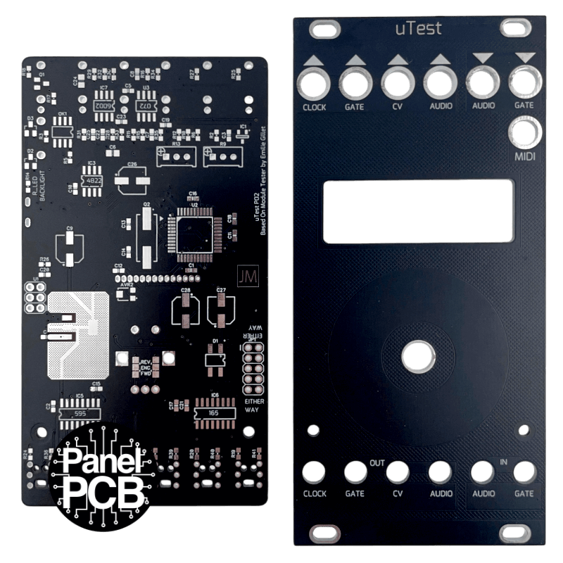
available
This is the panel PCB version of this kit.Eurorack version of the Mutable Instruments module tester.This eurorack module has the funcionality of the mutable instruments module tester, but with out the power supply for your module under test.DIY-Kit-Type:Panel/PCB Kit. This is a do-it-yourself panel/PCB kit, no parts are supplied, you will need to source them yourself.

available
Features:Four in one...ADSR envelope generator• Segment durations ranging from 0.2ms to 8s.• Quartic attack, exponential decay, exponential release.LFO and tap-tempo LFO• 0.03 Hz to 160 Hz.• 5 basic waveforms: square, triangle, sine, stepped, random.• Waveform variations and morphing for each of these: PWM, slope, folding/harmonics, step size, interpolation.• Phase at reset control.• Tap LFO can lock onto irregular rhythms.Drum synth• Channel 1: 808 kick model with extra parameters (tune, punch).• Channel 2: 808 snare model with extra parameters (tune, decay).• Channel 2: A specific combination of settings transform the snare into a modelled 808 hi-hat.Control modes• Twin: Channel 1&2 share the same parameters but can be triggered independently.• Split: Channel 1 is edited by knobs 1&2, channel 2 edited by knobs 3&4, with a simplified 2-parameter control scheme.• Expert: Channel 1&2 are completely independent.DIY-Kit-Type:PCB only Kit. This is a do-it-yourself PCB kit, no parts or Panel are supplied, you will need to source them yourself.